|
|
|
|
|
Modified RC servos are perhaps the most popular motors used in hobby robotics. No other kind of motor has
similar availability, price and possibilities. Some use them unmodified, some only modify them for continuous
rotation (which is sometimes called half-lobotomy), but the best control becomes possible if the motors
suffer full lobotomy first - when you remove everything except the motor and gears. Of course a proper H-bridge
and control circuit is necessary in this case.
For any advanced task that involves wheel rotation it is necessary to have some feedback from the wheels.
The control program must know how far the wheel rotates to adjust rotation speed of different wheels, or just to be sure that the
vehicle is standing still and not being pulled somewhere by an unknown force. My Akipaki robot
needs them to be able to move in a straight line and to be able to detect that the main control loop is undercompensating the fall
and it keeps rolling instead of standing or rocking around one place.
There are different types of shaft encoders hobbyists tend to use. I've seen a lot of designs where a pattern is printed
out on the wheel itself and a photosensing circuit is mounted somewhere on the chassis - this kind of design seems weird to me,
after all you don't carry your guts around, you keep them in the belly. Some more advanced
designs implement quadrature encoders, sometimes even fitted inside of an original gearhead motor chassis.
Although quadrature encoders give higher resolution and allow to detect the direction of spin, they usually depend heavily
on rarely available parts, because the circuit is bound to be extremely small. Also, quadrature encoder is not required
in case of a modified servo because the gear reduction ratio is so high that it's almost impossible to turn the motor
by rotating the output shaft. We can very safely assume that the direction of rotation always follows control and if it doesn't
we couldn't possibly help it anyway.
A design that I found to be most suitable for my needs belongs to Alan Macek. He used servos very similar to those
that I have and he implemented a very simple shaft encoder using only one precious unavailable part. The following
design is a further development of his ideas, there's very little original in my project. I use no unavailable parts
because if i did use any, I'd not be able to make it. If you have no problems finding QRB1114 or their likes, just feel
free to entertain yourself by watching me suffering.
|
|
|
I could not find any of so often mentioned on the net convenient and useful integrated IR emitter-receiver pairs specially designed for reflective
sensors. Neither could I find any parts of this sort that have integrated amplifiers in them. All that I had available were
regular IR emitters and phototransistors. So I had to adopt the circuit a little bit to make a use of what I have.
Here is my circuit. It explicitly has power filter to avoid hard noise that may be caused
by long wires, interference and whatnot is there in a motor. R4 is 680 ohm in my case, but it must be chosen experimentally
for your IR emitter/receiver combination. It also heavily depends on the kind of non-reflector you're using (more on that later).
Alternatively, sensitivity can be changed by altering R1/R2, but I haven't tried that. Provided you're capable of making experiments
to find suitable values, any kind of emitter/transmitter can be used - pick the cheapest ones your retailer has to offer. And
since the entire thing will sit inside of a black case, it's not necessary to use parts with visible light filters.
|
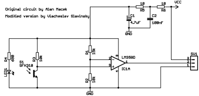 |
Fig.1 Circuit (click) |
|
|
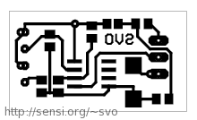 |
Fig.2 Phototemplate (click for PDF) |
|
I designed a template for PCB that would fit inside of a servo motor. Unfortunately I threw the original servo brains out
(after eating the most delicious parts of course), so I wasn't sure of their original size. But this design fits in pretty well,
with a help of a file and a hammer anyway. You can use the provided PDF file to make your own PCB's. Just like the one pictured right.
This board is so small that I could not find place to put any obnoxious texts on it...
N.B. The boards I made have a (non-fatal) error, a trained eye will spot them immediately. The template given here
has this error corrected.
|
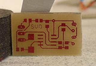 |
Fig.3 Just etched |
|
|
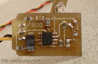 |
Fig.4 Populated board |
|
Here's what a populated board looks like. I didn't wash it after soldering and debugging, so it may look not
as fancy as a factory made one, but it definitely looks authentic, especially with mismatched sizes of salvaged SMD components.
Note that although this board is single-sided,
the reverse side is still present and is used a ground plane. It is necessary for interconnections and it also serves
as an EMI shield. On this picture it is visible that small square of the backplane (to the left-top) is removed
to avoid possible short circuit of wires.
|
|
|
It is now time to think about how to mount discrete parts into the casing of a servo. If we had one sender-receiver
module, we'd just cut a hole in the case and glue it in somewhere. But with two separate parts, it is really important
to keep them aligned together. I used some of remaining cuts of copper-laminated fiberglass to make a harness. You
would have to make two markings at proper distances to fit two 3-mm led-like things, then drill very small holes for
alignment, then take your big drill and make 3mm holes to fit in the led and the receiver. I made the holes so that
the emitter and the receiver are looking towards eachother, kind of simulating them being "focused" to a certain distance.
But I'm really not sure if this works and important at all. The emitter led seems to be shining pretty much omindirectionally
at a distance this small. After some simple testing (the circuit output must go down from high when something reflective
is near the sensor) I glued both components to the harness and soldered short wires to attach them to the PCB permanently.
|
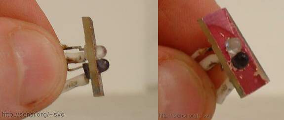 |
Fig.5 Harness |
|
|
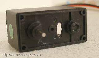 |
Fig.6 Sensor window |
|
On the left picture you can see a window in the casing, the sensor will "look" through it on the gear with interrupter
(this is a view with reductor gears removed, but you must know that if you went this far into servo anatomy).
The right picture shows the bottom side of the "encoder wheel". The real benefit of this design is that the encoder
wheel is really simple and doesn't require complicated printed patterns (although you can try that, I don't recommend
because this wheel is really small, I barely could photograph the pest). You can see traces of all kinds of tortures
I tried on this poor gear. In the end of this ordeal I went completely medieval and glued onto it a tiny patch of
insulation tape made of pitch black fabric.
Painting the gear with marker didn't give enough contrast. Even glueing a piece of paper all blackened with a pen didn't
give enough contrast - at distance this close everything except pitch black blastic is very reflective for IR. Actually
glueing a tiny bit of plastic from SMD reel packaging would work too.
|
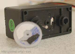 |
Fig.7 Encoder wheel |
|
|
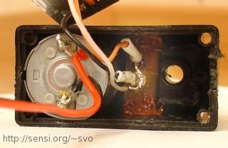 |
Fig.8 Gooed in |
|
Left picture shows how the harness is fitted inside of the servo casing. I used some kind of thermal glue. It's
not exactly the kind used in glue pistols, it's not transparent and messy and smells funny. Any glue will do though.
Right picture shows how the makeshift sensor is peeking through the peephole in the casing. Just a little more time
and all it will ever see will be the torture encoder wheel. Har.
|
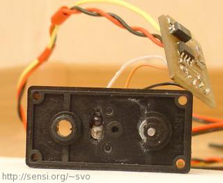 |
Fig.9 Peek-a-boo |
|
|
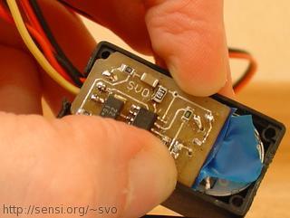 |
Fig.10 Packing |
|
Everything must be clear from now on. I had to cut the board a little on the sides to let the screws fit in. Protected it
with two layers of insulation tape to avoid any contact with the motor, then fitted it in. The capacitor was the most
protruding part on the board, I even had to cut a little window in the cover for it too. But still, the board is a little
thicker than the casing allows, after I screwed back the cover the servo looks a little oversatiated.
With this reductor (the original servo was Hi-Tec HS-311, they say it's the most unmodifiable servo ever made, but I
don't understand why - I modified the hell out of it and it still works), I get 42 pulses per output shaft revolution.
The duty cycle is not perfectly 50% as you might guess by looking at the encoder wheel I use.
Number of pulses per revolution can be increased at least two-fold by adding another nonreflective stripe of black goo.
|
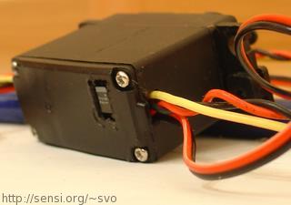 |
Fig.11 Fat boy |
|
|
|
Conclusion: this design is relatively simple to implement and it works with the most unmodifiable servo in the world.
Number of pulses per revolution has sacred meaning which can not be a bad thing. After the value of current-limiting resistor for
certain type of emitter/receiver is found, the entire thing must be easy to reproduce for as many motors as needed. No hard-to find
or expensive components are necessary, and the entire modification fits completely into the original servo case.
|
|
|
|
|
