Motöri The Plotter
Motöri the Plotter
I have always admired pen plotters since the first time I saw one. I was a little kid back then and I didn't even know a thing about computers. Unfortunately, as I grew up, the plotters got completely phased out so I never really had a chance to play with a real plotter. Now it was about time I'd built my own plotter. With black jack and hookers.
Plotter Basics
A traditional flatbed plotter, of which Motöri is an instance of, consists of a 2D coordinate table which delivers a pen-holding carriage to any position within the plotting area. Carriage has a mechanism that can move the pen up and down. When the pen is down and carriage is moving, a trace on paper remains. That's how vector graphics used to be drawn before the raster plotters took over. A pen holder can also hold a knife, that would be a cutting plotter to cut out signs and labels. Or there could be a laser and it could be used to engrave on things.The gantry consists of a frame that supports rails or guide rods that constitute the X axis. Pillow blocks travel back and forth on these rods, and they are carrying another pair of rails and that pair of rails would be the Y axis. And along the Y axis travels the carriage with a pen. You might call the pen actuator a Z axis, but it would be disrespectful of CNC machines because it basically has only two positions: up and down.
XY plotters share a lot in common with 3-axis CNC machines. A CNC machine can be used as a plotter, but it would probably be slower because CNC machine is designed to be rigid and precise. A plotter probably can't be used as a CNC machine, because a typical plotter design sacrifices a lot in favour of build simplicity and speed: pen is not a very heavy tool.
The things that travel along the axes are moved with motors. The motors are moved by special motor driver and the driver is commanded by a microcontroller that interprets the data sent in by the host computer, e.g. a HPGL file describing a graphics. HPGL file is normally a sequence of instructions. Typically there would be some setup instructions at start, followed by commands like "PU; PA 4,8; PD 15,16,23,42;PG;". This sequence would raise the pen, move to absolute position 4,8, lower the pen, draw two strokes to (15,16) and then to (23,42), raise the pen and go home (eject the page, so to speak). HPGL files can be generated by various CAD and drawing programs, or converted from other vector graphics format like PostScript, PDF or SVG.
Parts
Motöri is built from parts salvaged from old printers and scanners, this puts some constraints on design decisions. After some hunting these parts were collected:- two bipolar stepper motors
- timing belts and tension pulleys
-
precision hardened shafts, all different
-
carriages, perfectly matching the shafts
- power supplies
- plenty of springs, pieces of plastic
Mechanics
The Axes
It makes absolutely no sense to describe the mechanics in much detail because every build decision depends on the kind of junk you've got, tools you have and your skills. I'm not an awfully good builder and I don't have any serious tools, so similar build must be pretty easy to reproduce. What I did was built with a tiny Proxxon table saw, a small drill press and a larger drill on a pretty shaky stand. A personal observation: even a very poor drill stand is better than no stand at all.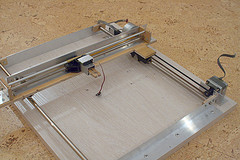
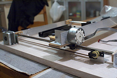

A note on the X-drive mechanism. If the side of the bridge opposite to the driving motor uses a pair of plain bearings instead of a crawler like in my design, it's going to get stuck. A good solution to this, which is better than the one I'm using, is to make the X-motor drive it from the both sides. But it would then require an additional set of pulleys and a timing belt, etc. Another solution is to make a cord arrangement like in an etch-a-sketch. Or you could try to design it in such a way that it will be pulled in the middle, this will work too. The quality of this part defines maximum starting and stopping speed of the X axis. If it overshoots and oscillates, slower X-speed may solve the problem.
Y-axis is a little easier because the mass it carries is much smaller.
Pen Carriage
 The pen carriage is just as important as everything else. It must be rigid enough to carry out pen movement and pressure and it's better when it's lightweight, because that means less inertia and higher speeds. In my design I used one good rod and one crappy rod. If I had two good rods, I'd use two.
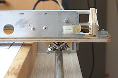
I was looking all around the internets and found almost nothing about pen lifting. Every plotter builder would cleverly hide the details of pen holder/lifter, pretending that it actually works and it was so simple that it's not worth a sentence or two. I tried different things myself, but this simple lever-pushed-by-a-servo-with-a-cam-on-its-shaft-tugged-by-a-rubber-band seems to work best. Servo life is short though and when I get a hold of a decent solenoid I would use it instead of servo.
Here's a technical drawing describing my method and apparatus for lifting a pen incorporated therein and lowering same. It's not perfect and pen loading is a nightmare. If you can do better, do better. The basic principle is probably going to stay the same: it's a lever, the short side of it is pushed by a cam mounted on a shaft of a RC servo. It's made in such a way that when servo pushes, the pen is lifted up and when servo doesn't push, the pen-side of the lever is pulled down by the weight of the pen + the force of the spring. This allows for some adjustments in pen pressure, while keeping it simple. A lever is not really necessary, but it converts power, which servos have a plenty, into speed, which cheap servos are short of.
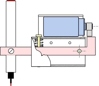
A big disadvantage of this design is the nonlinear motion of pen. It adds extra momentum, especially with long pens and this may result in crooked lines. Besides, the pen tip follows a circle in air every time the pen is lowered and raised and if the drawing surface is not perfectly flat and rigid, it could create extra little strokes where the pen hits the paper.
When you see some internet plotter project without any actual plots shown, this is because the author failed to implement a proper method and apparatus.
Electronics
Motöri uses motors salvaged from relatively new (about 10 years old) equipment and those are bipolar steppers with pretty large step angles. This means that a special driving circuit is absolutely necessary to simply drive them: for that 2 H-bridges per motor would suffice. But large step angles and direct drive means that microstepping is also a must, otherwise the resolution of the plotter would be about 1-2mm. Good thing we have Allegro to save us all and in this controller two A3984 microstepping drivers are used. They are designed specially for brave lazy people who are always ready to sacrificeThe motor drivers only can do µ-step forward/backward and hold position. A microcontroller is still necessary to interpret the data coming from the host PC and translate it into low-level step commands for the motor drivers. That would be an ATmega644 because it seems to have the right combination of the amount of I/O pins, program memory, RAM etc. It's rated for 20MHz operation and in Motöri it's clocked at 18,432 MHz. A frequency like that is convenient because it allows all possible baud rates at 0% error rate.
The USB-serial connection is done via the now ubiquitious FT232RL. Plotters are teh slow, so flow control is necessary: RTS/CTS flow control is implemented in firmware.
Connectors are provided for the stepper motors, the servo, end switches and 4 of other high-voltage actuators switched by the proverbial ULN2803A in DIP package. For example, a 24V solenoid can be used instead of a servo to move the pen.
There are no blue leds used in this design, but there are extra remaining pins that can be used for illumination or hooking up a display or some buttons. For example, a [Pause] button can be really handy.
To provide the power for logic and motors, a power supply from one of the cannibalized printers is used. It's a nice fully isolated brick that provides +5V for the logic and the pen servo and +24V with enough juice for both steppers.
Links:
- EAGLE CAD design files
- Schematics in PDF
- PCB layout in PDF: top bottom
PCB
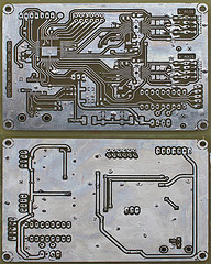 The PCB is designed with home making in mind. It's double sided, but the other side is kept to minimum and the traces are really thick to make alignment less critical. Vias are large and the pads are made as fat as possible too. Also, to make connector soldering easier, I have a via next to every connector pad. That adds a lot of extra drilling, however. You can avoid this by just putting the connectors on the other side of PCB. For vias, I drill 0.6mm holes, then take a through-hole resistor pin or similar piece of wire, push it through, cut it short and hammer down: that makes my vias riveted. After all rivets are done, I apply extra flux over them and make sure that they're all soldered down for long-term reliability. It should be no problem to order this PCB from a board house, too, but you'll seriously miss out on all the fun of making your own PCB. You get extra bonus for plotting this PCB on a homemade plotter.
Assembly and Tuning
A3984 are produced in eTSSOP packages. That little "e" means that they have a special thermal pad at the bottom of the package and the bad news is that it really has to be soldered. I solved this by drilling large holes in my PCB exactly under the chips, putting some solder in them and poking there with my soldering iron. It's not a very hi-tech method. A heat gun can be used with care, too.There's not a lot to be tuned in this circuit. The only thing that requires adjustment is the Vref that defines maximum current passing through the motor coils. It should be found experimentally, starting with smallest possible value (set the wiper to the low side). If Vref is too low, the motors will fail to move and the driver chips may overheat. If the drivers or current-sense resistors are hot, something is wrong. For example, if Vref is too low, the motors will move in full steps without load, but will fail to do microsteps and that will drive the control circuits nuts and the chip will be abnormally hot. If Vref is slightly higher than that but still not there yet, the motors will respond to microstepping but will fail to hold position, which will result in the failed attempt to compensate in the driver and overheating. When tuned correctly, the circuit must stay cold. Hot is bad, mmkay.
If assembled properly, there are no solder bridges or unsoldered pins, everything should "just work".
Bootstrapping
Some people love ISP and don't like bootloaders. I hate ISP on AVR because it's the fastest way to burn the chip or screw up the fuses. First thing I do after powering the circuit up is: program the chip with a suitable bootloader, remove the ISP programmer and never touch it again. In this design I use STK500-compatible bootloader that can be found here, along with instructions about using them. After it's installed, the firmware can be loaded with avrdude or AVR Studio via the USB-serial connection.Firmware
The firmware is as is, open source, with a BSD license which means that you can do whatever you want but don't forget me, the author. Thanks.It should compile with avr-gcc, or WinAVR without a squeak. And there is some documentation inside.
Links:
- Source code
- Online documentation is sometimes up-to-date
HPGL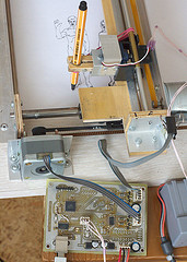
The HPGL subset supported by Motöri is very limited. It should be able to correctly plot files generated by pstoedit and EAGLE HPGL driver. Complex HPGL plots from other programs can be translated into simplified HPGL by hp2xx, but hp2xx has a tendency to scramble nice plots and convert simple curves into hundreds of separate strokes, mess up with dimensions and so on. I don't really recommend it.The list of supported HPGL commands is maintained on this wiki page.
The implementation of them is not really complete and perhaps is not accurate. I only did what was required to draw the files I was able to produce. I used this HP-GL Reference Guide as my primary source of information.
Results
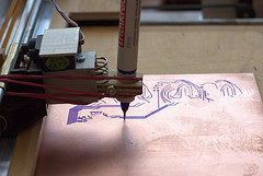
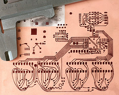
I continue development of this plotter and results change. It produces nice drawings, e.g. exported from Inkscape in postscript and then converted into HPGL by pstoedit. The precision is hard to gauge properly. It's probably not insanely high, but it is possible to produce a sensible PCB pattern with a 0.8mm pitch TQFP on a piece of copper clad board, but the board has to be designed with limitations in mind, for example the traces can't go too close to each other. It is not going to be a very practical method of PCB making in general, because: the precision is still much lower than what you get with a laser printer; the etch-resistant pens, CD markers etc are relatively thick, they wear quickly and they are not very etch-resistant; the set-up process is a little bit awkward and not very quick. The design could use some improvement yet, too. For example, there's a lot of overshooting in the X-axis movement, or the process of fixing a pen in the holder could be less cumbersone.Here are some drawings produced by Motöri on various stages of development:
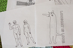
A 300mW laser module is on the way, and that's where the real joy is going to begin.
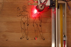
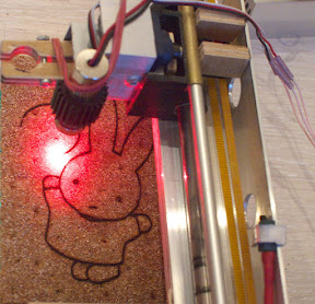
Update: 300mW Laser
The 300mW laser is not as powerful as I'd like it to be, but it can cut thin films, bite some 10-12mm into high density foam and pyroengrave wood.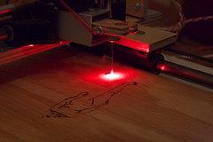


—-—
Адрес этой статьи: https://caglrc.cc/motori/
Просьба указывать ссылку на первоисточник.
Copyright © 2009 Viacheslav Slavinsky svofski on gmail
Updated:
Fri Sep 30 11:37:43 UTC 2016