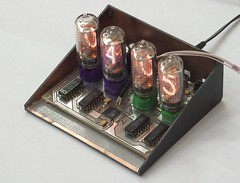
Patashnik: a Nixie Clock
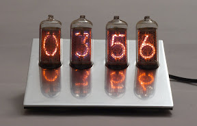 Nixie Tubes: ИН-8-2
Microcontroller: ATmega8535
RTC: DS3234 TCXO
Power Supply: 7-12V
Power
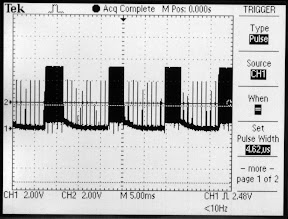
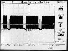
A boost converter is used to make the high voltage for nixie tubes. It's important to get a MOSFET with smallest possible gate charge, the fastest possible diode and the tank capacitor must be a low ESR type. The boost converter is pumped by the microcontroller, hardware waveform generation is used and OC1A output is connected to the gate. Closed loop goes to the ADC via a voltage divider with 1:100 ratio. Output voltage is not proportional to the frequency and duty cycle, so the regulator simply turns pumping on or off to keep the voltage near desired setpoint. Pulse frequency and duty cycle were found experimentally to get maximal efficiency, but minding temperature of the components. A circuit comprised of C2, R1 and D2 guarrantees closed gate in case of a failure (or reprogramming).
Closed-loop control allows dynamic change of output voltage. For example, when the tubes are working at low brightness (short duty cycle), their drive voltage is raised above normal to ensure that all digits are fully lit. When duty cycle is above 2/4, all cathodes light up at lower voltages. Voltage regulation lets the circuit work in optimal modes, keeps the components cool and makes tube life longer.
Displays
155ID1 drivers can blank the nixies if a value between 10102 and 11112 is at their inputs. This allows pulsing the tubes, changing their brightness by adjusting duty cycle. This clock has 4 fixed brightnessCompensating the imperfection
 Nixie tubes have differ very much one from another. Some tubes would light
up much brighter than average, while others would fail to fully light
certain digits at same voltage. Thanks to selective blanking, this can
be accounted for and partially compensated. For the too bright tubes,
their relative duty cycle is shortened; tubes that are harder to light
up get longer pulses. When switching to the "hard" numbers, voltage is
raised minutely for a brief period of time to allow the cathode to light
up fully, then lowered back.
Nixie tubes have differ very much one from another. Some tubes would light
up much brighter than average, while others would fail to fully light
certain digits at same voltage. Thanks to selective blanking, this can
be accounted for and partially compensated. For the too bright tubes,
their relative duty cycle is shortened; tubes that are harder to light
up get longer pulses. When switching to the "hard" numbers, voltage is
raised minutely for a brief period of time to allow the cathode to light
up fully, then lowered back.Real Time Clock
Patashnik uses no crystal. The microcontroller is clocked at 8 MHz by its builtin RC-oscillator. This precision is enough for everything the micro does. All chronometric functions are perfromed by the DS3234 temperature-compensated real-time clock, which is promised to have only about 1 minute deviation over a period of one year. There's no data display, but the calendar is kept up to date to facilitate automatic daylight saving transitions. When Patashnik's umbilical is unplugged, its clock keeps running from a small lithium battery.Enclosure
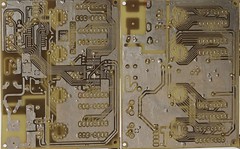
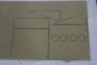
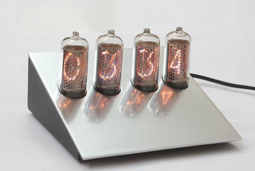
The enclosure is made from a single-sided copper-clad fiberglass board and painted.
⇓
⇓
Files
References
- MAX1771-based high-efficiency Nixie power supply
-
 DS3234 Extremely Accurate RTC with SPI Bus, Integrated Crystal, and SRAM
- How to build a Nixie Clock (Tutorial on AVRFreaks)
- Часы на газоразрядных индикаторах ИН-12Б (РадиоКот)
-
Слонс (aplomb.nl)
- Switching Power Supply Design (aplomb.nl)
-
История паташника в классическую эпоху (Топос)
- Patashnik (Alone) (cgsociety.org)
- Patashnik by Señor Salme