Strobeshnik
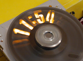
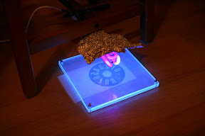
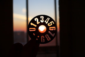
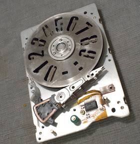
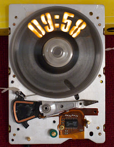
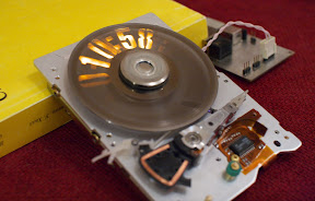
A Digital HDD ClockStrobeshnik uses stroboscopic effect to create the illusion of persistent numeric display. The hard drive platter has 10 digits, colon and dash marks, cut all the way through it. Behind the platter, in the HDD chassis, there is a PCB with groups of diffused LEDs. Groups of LEDs in each character position can be strobed independently at any given time. By careful timing of the light strobes, an illusion of still-standing numbers can be created.
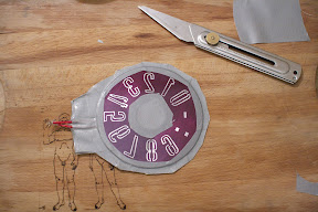
Making Of The Number Platter
I designed the template in Inkscape. Haettenschweiler typeface is the base for my digit outlines, but I had to skew the characters to make them better fit the narrow angular segments of my display.The aluminium platter with digits was etched galvanically. I tried many times before I got a satisfactory result. I tried chemical etching in ferric chloride, but FeCl3 would etch sideways way too soon and the result will be unacceptable. After about 6 (six!) attempts, the technique is like this:
-
Sand off/grind away/mechanically remove 10 microns of protective and ferromagnetic material from the top side of the Al platter until aluminium is fully exposed
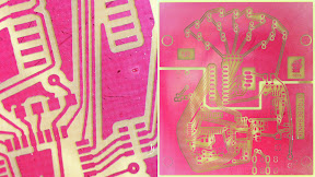
- Apply photoresist, expose, develop
- Connect wires and thoroughly seal sides and edges with tape
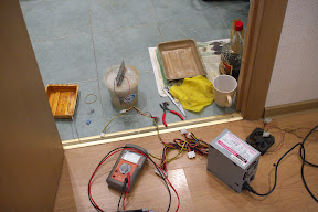
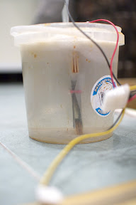
- Etch in a mild electrolyte of NaCl with 5V power from an ATX power supply, the other electrode was a piece of zinc plated iron, the distance between electrodes about 5-7mm. Etch time is about 30 minutes until the foil of the reverse of the platter is exposed.
Balancing
Balancing is something I didn't do well. I wrote a little Python script that would calculate the new centre of mass of the altered platter, using my original phototemplate picture. All I got was a point of the new centre of mass which is really of little help, except that it confirmed the idea that weight should be added opposite of the least-empty characters, near the digit 5. Compared to other imperfections, this one is really minor.Circuit and software
A single ULN2803 is used to switch all leds (5) and all motor coils (3). It was tempting to use one IC for all switching because I had a plenty of them. But it was a poor choice because ULN's really can't handle large currents. After burning 3 chips in a row, with a help of a friend I learned about piggybacking trick. Soldering a second ULN2803 on top of the original one really did the trick. One should never use ULN2803, especially not for the motor control.
A high-side current sensing network is conceived, but it never was implemented. Probably clever and fast sensing might help me with spin-up and avoid burning the ULN's, but eventually I ended up with a fully open loop circuit which only uses empirical data to spin up the motor.
I learned it the hard way that high-frequency PWM is essential for quiet motor operation. Strobeshnik makes a pretty rough shrieking noise now because it runs the coils at 1/6 duty cycle and has to switch them at approximately 120Hz. A better choice would be to have an additional high-side MOSFET switch driven by one of the AVR timers, that would allow much faster switching speed, far out of the audible range. This is planned but not yet done.
Instead of an index hole, Strobeshnik uses reflective sensing. There's an IR LED and a phototransistor pair mounted under the outer rim of the platter. A thin piece of black foam absorbs IR light and it generates a fairly sharp negative pulse on the output of the phototransistor. I used a similar method in my modded servos, and I like such method better than index-hole, because it allows all components to be mounted on the PCB.

The index mark generates INT0. The interrupt handler adjusts the full-turn cycle count if the position is not matched until it is. Visually it can be observed as digits drifting around unil the correct position is set.
Results
This is an awesome piece of hackage that tends to impress people. Unfortunately it fails at being quiet and reliable, which is a very important quality of a useful timepiece. Strobeshnik makes an awesome exhibition item however and can be classified as art.Strobeshnik spins at approximately 30 rotations per second, which is very close to 30 fps of the camera. I couldn't capture long fragments of time display without annoying blinking. A stroboscopic display got strobed.
Stuff to see and download
—-—
Address of this page: https://caglrc.cc/strobeshnik/
All Rights Reserved
Copyright © 2010 Viacheslav Slavinsky svofski on gmail
Thu Sep 29 22:45:18 UTC 2016