Using FPGA To Count Coil Windings
In the days of yore amateurs used to hack a calculator to simulate a keypress to help them count the coil windings. Calculators are relatively rare and harder to tweak these days. There's an assortment of other awesome tools around however. For example, a Cyclone II development kit.
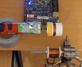
To count the windings we need a sensor that would switch every time our coil makes a turn. The simpliest sensor for this task is a reed switch. A reed contact can be switched on or off by moving a magnet near it. A small parking magnet salvaged from a HDD would do. Other requirements for this project are: tape, wires, a screwdriver, skills or lack of life.
Reed contacts are packed in tiny glass vials and they're extremely brittle. Be very careful when bending the terminals, do not stress the glass. Solder the wire ends, attach the reed to a plastic card, then tape the plastic card to the static part of the screwdriver chuck. Stick the magnet to the screwdriver shaft.
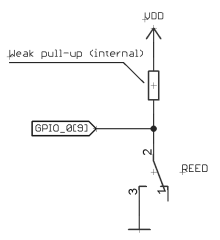
set_instance_assignment -name WEAK_PULL_UP_RESISTOR ON -to GPIO_0[9]
What this means is that the counting input is normally pulled up to be a logical “1” and on each turn the magnet will pull the contact in the relay and shorten it to the ground, making it a logical “0”. If your switch is normally closed, this picture will be reversed but it doesn't really matter because all we need is an edge. The polarity is not important.
The counter circuit will be described in Verilog HDL. There are several possible approaches to counting pulses. One would be to define an event that will increment a counter on every positive edge of input signal, which is like using our reed relay as a clock source. This is a rather poor way of handling things in FPGA. Instead we'll be working in the clock domain provided by the dedicated reliable clock source. The process clocked by the good clock will sample input signal and count the turns. Let's start with this code:
// reassign the input signals for convenience
wire clk = clk50mhz;                                // 50MHz onboard clock
wire reset = ~KEY[0];                               // reset, active high
wire reed = GPIO_0[9];                              // reed relay input

reg [15:0] turnscount;                              // the counter
reg        sensorsampled;                           // last sampled value

always @(posedge clk) begin
    if (reset)
        turnscount <= 0;
    else begin
        // sample current value
        sensorsampled <= reed;
        if (~sensorsampled && reed) begin
            // current value is 1, last sample is 0 --> positive edge
            turnscount <= turnscount + 1'b1;
        end
    end
end
This circuit samples the input and increments the counter on every positive edge. It is functional and it will work, but it will behave a little funny. The troublemaker is the contact bounce which happens even in vacuum switches. Clocked at 50MHz the circuit registers dozens of bounces per reed switching, or shaft revolution. To work around this problem, let's sample the signal a little slower. Say, 262144-fold slower, the sampling frequency will then be 190 Hz.
reg [17:0] slooow;                                  // division register
wire       slow_enable = slooow == 0;               // slow enable

// this process counts the clocks to produce slow_enable
always @(posedge clk) begin: _slow
    slooow <= slooow + 1'b1;
end
wire plus_one = ~sensorsampled && reed;             // sample positive edge

always @(posedge clk) begin
    if (reset)
        turnscount <= 0;
    else
        if (slow_enable) begin
            if (plus_one) turnscount <= turnscount + 1'b1;
        end
end
To display the value, a standard 7-segment encoder which can be found in the development kit example projects is sufficient:
SEG7_LUT_4 seg7display(HEX0, HEX1, HEX2, HEX3, turnscount);
This turns counter will work very well and one could call it a finished job. However, people tend to count in base-10 so let's make the counter people-compatible. Starting with a single decade with decimal carry:
// syncrhonous decade counter with reset and carry out
module decade_counter(input clk,
              input ena,
              input reset,
              output reg[3:0] value,
              output c);

assign c = value == 9;

always @(posedge clk)
    if (reset)
        value <= 4'b0;
    else if (ena)
        value <= value == 9 ? 0 : (value + 1'b1);

endmodule
Then group four decades into one counter in the main module:
wire [15:0] bcd_turns;                              // turns counter bus (bcd)
wire        cy0,cy1,cy2;                            // decade carry flags

// instantiate one decade counter, increment on plus_one & slow_enable,
// the output goes to bcd_turns[3:0], carry out in cy0
decade_counter ctr0(.clk(clk), .ena(plus_one & slow_enable), .reset(reset),
                    .value(bcd_turns[3:0]), .c(cy0));

// next decimal place, minding carry from previous position
decade_counter ctr1(.clk(clk), .ena(plus_one & slow_enable & cy0), .reset(reset),
                    .value(bcd_turns[7:4]), .c(cy1));
// ...
decade_counter ctr2(.clk(clk), .ena(plus_one & slow_enable & cy0 & cy1), .reset(reset),
                    .value(bcd_turns[11:8]), .c(cy2));
// ...
decade_counter ctr3(.clk(clk), .ena(plus_one & slow_enable & cy0 & cy1 & cy2), .reset(reset),
                    .value(bcd_turns[15:12]));
And the display decoder will be driven by the bcd_turns bus instead.
SEG7_LUT_4 seg7display(HEX0, HEX1, HEX2, HEX3, bcd_turns);
And this completes the project, we have a fully functional coil-winding tool now. Here's the project for the DE1 kit available for download. The Verilog code can be used with any other development board, Altera or Xilinx alike, but the project, assignments and settings might need to be adjusted correspondingly.