voltage.h File Reference
Boost converter closed-loop control. More...
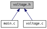
This graph shows which files directly or indirectly include this file:

Go to the source code of this file.
Functions | |
| void | pump_init () |
| Setup PWM output for the boost converter. | |
| void | adc_init () |
| Init ADC converter and ADC interrupt. | |
| void | pump_nomoar () |
| Terminate boost converter operation. | |
| void | voltage_adjust (uint8_t flag) |
| void | voltage_adjust_tick () |
Variables | |
| volatile uint16_t | voltage |
| voltage (magic units) | |
| volatile uint16_t | voltage_setpoint |
| voltage setpoints (magic units) | |
Detailed Description
Boost converter closed-loop control.
Setup routines for boost converter pulse generation and implementation of the closed control loop.
Function Documentation
| void adc_init | ( | ) |
Init ADC converter and ADC interrupt.
00081                 {
00082     voltage = 0;
00083
00084     // PORTA.7 is the feedback input, AREF = AREF pin
00085     ADMUX = 7;
00086     DDRA &= ~_BV(7);
00087
00088     // ADC enable, autotrigger, interrupt enable, prescaler = 111 (divide by 32)
00089     ADCSRA = BV6(ADEN, ADATE, ADIE, ADPS2, ADPS1, ADPS0);
00090     //ADCSRA = BV5(ADEN, ADIE, ADPS2, ADPS1, ADPS0);
00091
00092     ADCSRA |= _BV(ADSC);
00093 }
| void pump_init | ( | ) |
Setup PWM output for the boost converter.
00017                  {
00018     // set fast pwm mode
00019     // COM1A1:0 = 10, clear oc1a on compare match, set at top
00020     // COM1B1:0 = 00, normal port operation
00021     // no FOC
00022     // WGM11:10 (WGM = Fast PWM, TOP=ICR1: 1110) = 11
00023     TCCR1A = BV2(COM1A1, WGM11);
00024     TCCR1B = BV2(WGM13,WGM12);
00025
00026     OCR1A = 37;
00027     ICR1 = 50;
00028
00029     TCCR1B |= _BV(CS10); // clk/1 = 8MHz
00030
00031     DDRD |= BV2(5,4);
00032 }
| void pump_nomoar | ( | ) |
| void voltage_adjust | ( | uint8_t | flag | ) | [inline] |
Adjust output voltage for specific display contents and duty cycle. flag = 0 initiates adjustment. Logic is magic.
00047                                          {
00048     switch (flag) {
00049     case 0:
00050         if (on_duty == 4) {
00051             if (((time & 0x00f0)>>4) == 2) {
00052                 voltage_setpoint = 410;
00053                 cli();
00054                 voltage_delayed = 380;
00055                 voltage_delay_count = 64;
00056                 sei();
00057             } else {
00058                 voltage_setpoint = 380;
00059             }
00060         } else {
00061             voltage_setpoint = 400;
00062         }
00063         break;
00064     case 1:
00065         voltage_setpoint = voltage_delayed;
00066         break;
00067     }
00068 }
| void voltage_adjust_tick | ( | ) |
Must be called every tick from the main timer interrupt routine. After voltage delay is expired, sets voltage setpoint to postponed value.
00071                            {
00072     if (voltage_delay_count != 0) {
00073         voltage_delay_count--;
00074         if (voltage_delay_count == 0) {
00075             voltage_adjust(1);
00076         }
00077     }
00078 }
Here is the call graph for this function:

Variable Documentation
| volatile uint16_t voltage |
voltage (magic units)
| volatile uint16_t voltage_setpoint |
voltage setpoints (magic units)
 1.6.1
1.6.1